Shanel Wu
They/them. PhD student: smart textiles, weaving, computational craft, hardware hacking.
Voltage Regulators: A Refresher
by S
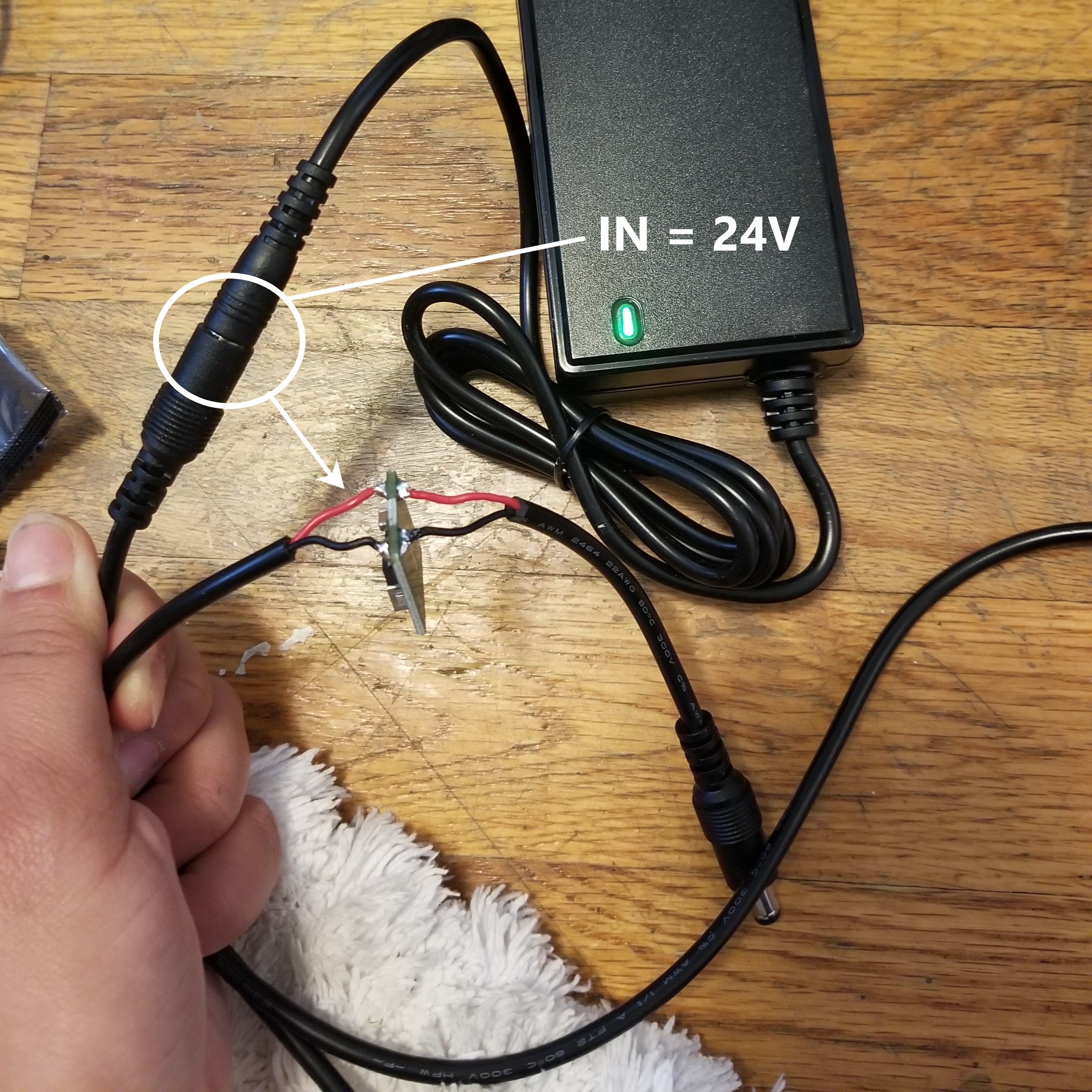
Continuing my exploration of cheap-o components from Amazon (link to the one I bought) for this sound-interactive project, I needed a way to supply multiple voltage levels from a single power socket, so voltage regulators to the rescue. Namely, I needed a speaker amp (VCC = 24V) and ESP32’s (VCC = 5V) to both run off of the speaker amp’s power brick.
I did NOT want to cut up the relatively-pricey power brick’s cord. So I additionally bought some barrel connector extension cords that would just link up between the power brick and the amp, and cut into those cords instead.
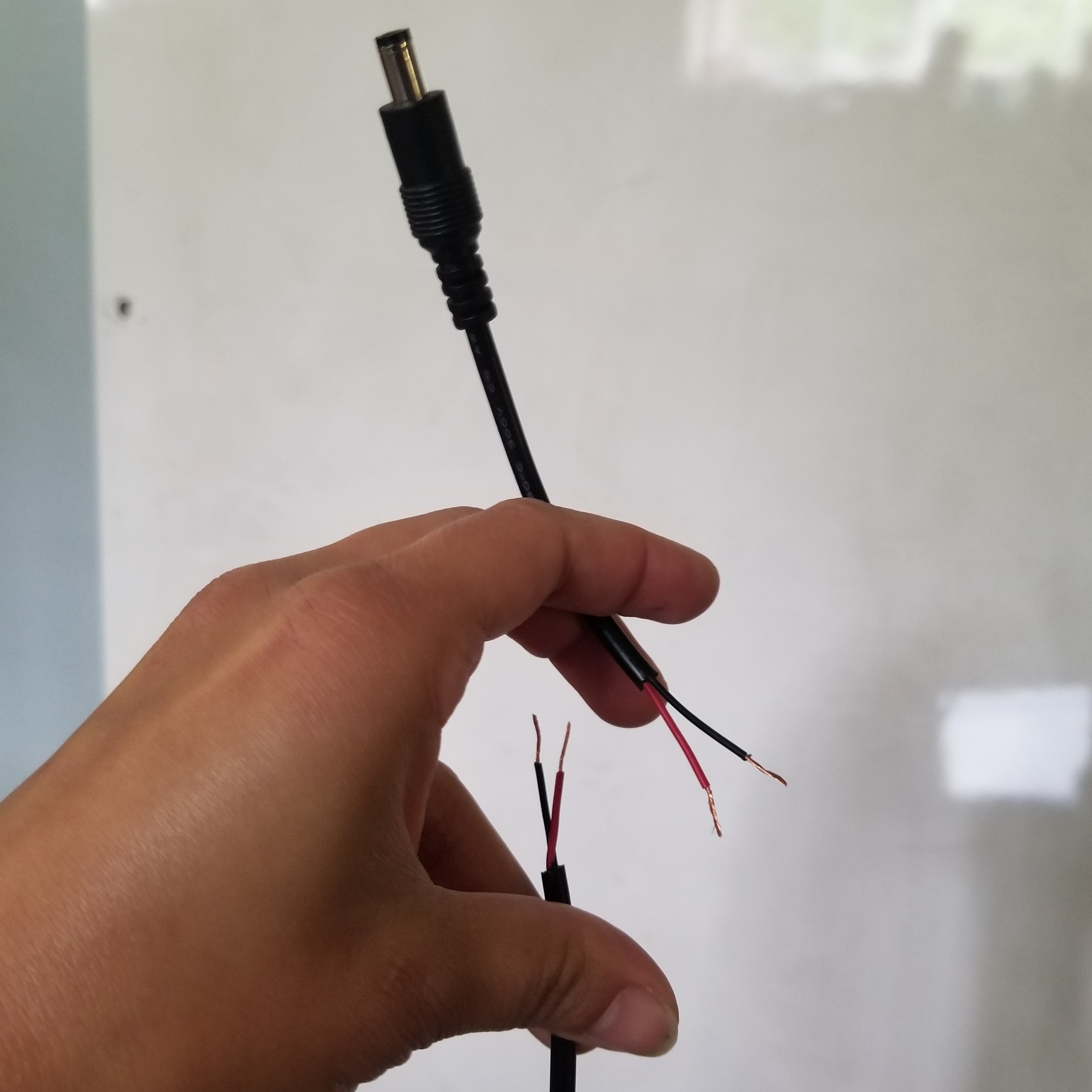
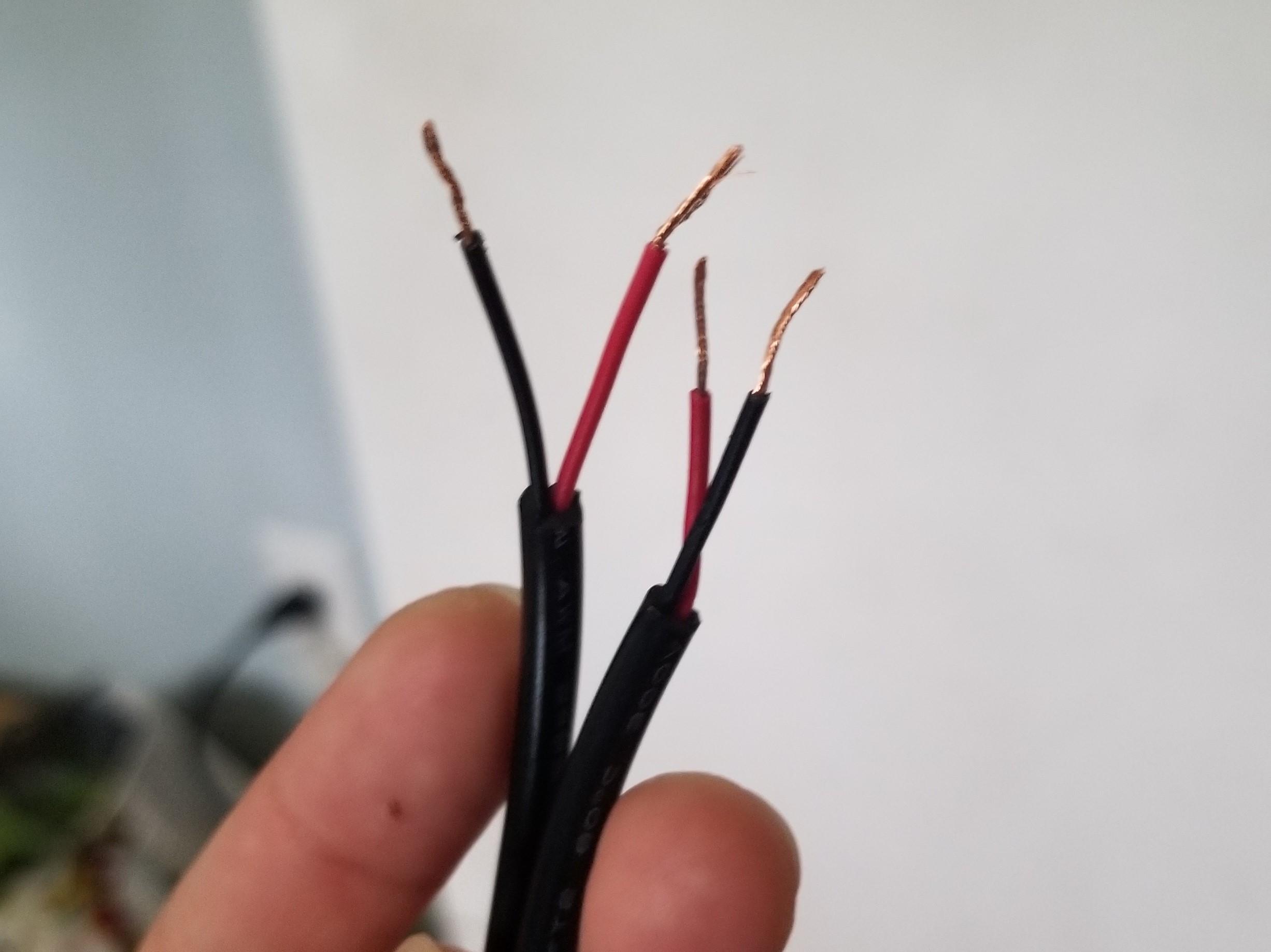
It’s a pretty standard power cord, so there are two wires: red (VCC) and black (GND), both of which need to have their ends stripped after cutting.
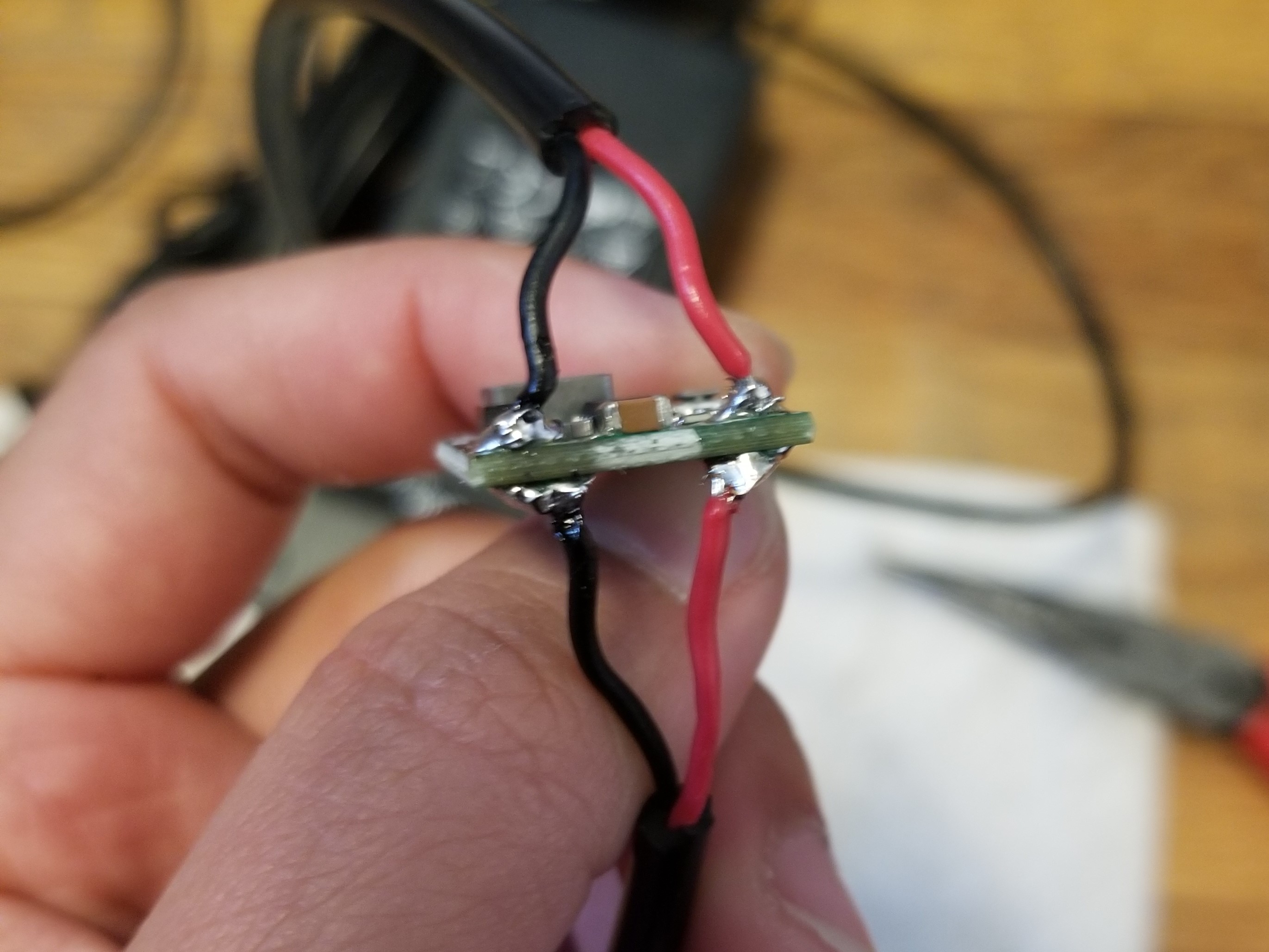
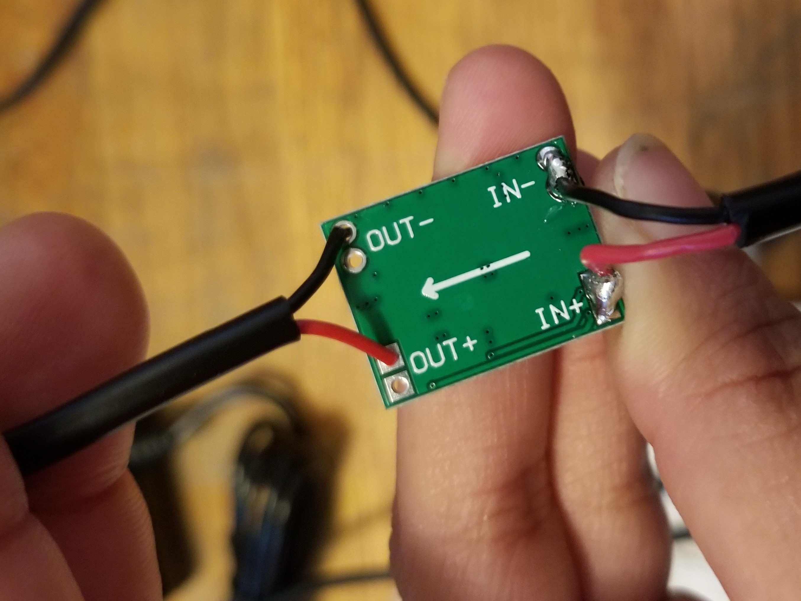
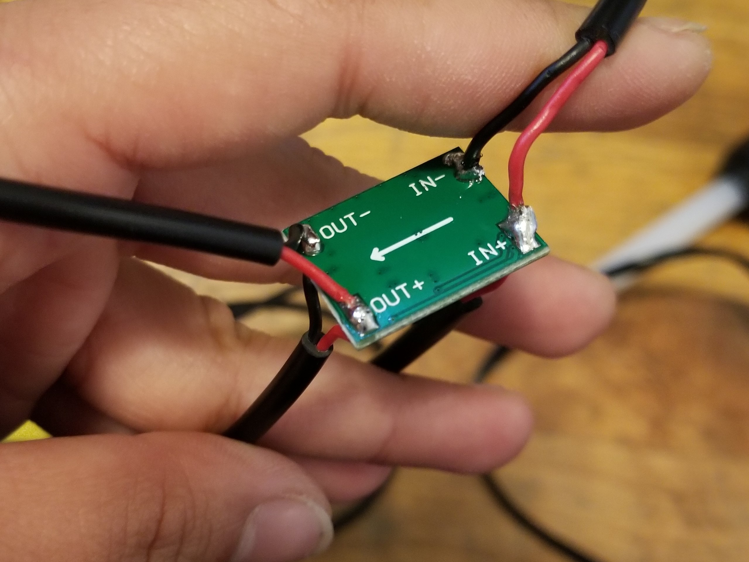
Now the cord’s ready to have the voltage regulator connected. Effectively, what we’re doing is tapping into the 24V supply to siphon off the ESP32’s smaller power supply. Since 24V is the input voltage, the barrel connector cord needs to go to the board’s “IN” side. This particular board has two holes at each connection point (IN + and -, OUT + and -), which makes it easy to insert a cut wire, connecting each end to the same point. I wonder if that’s an intentional design feature.
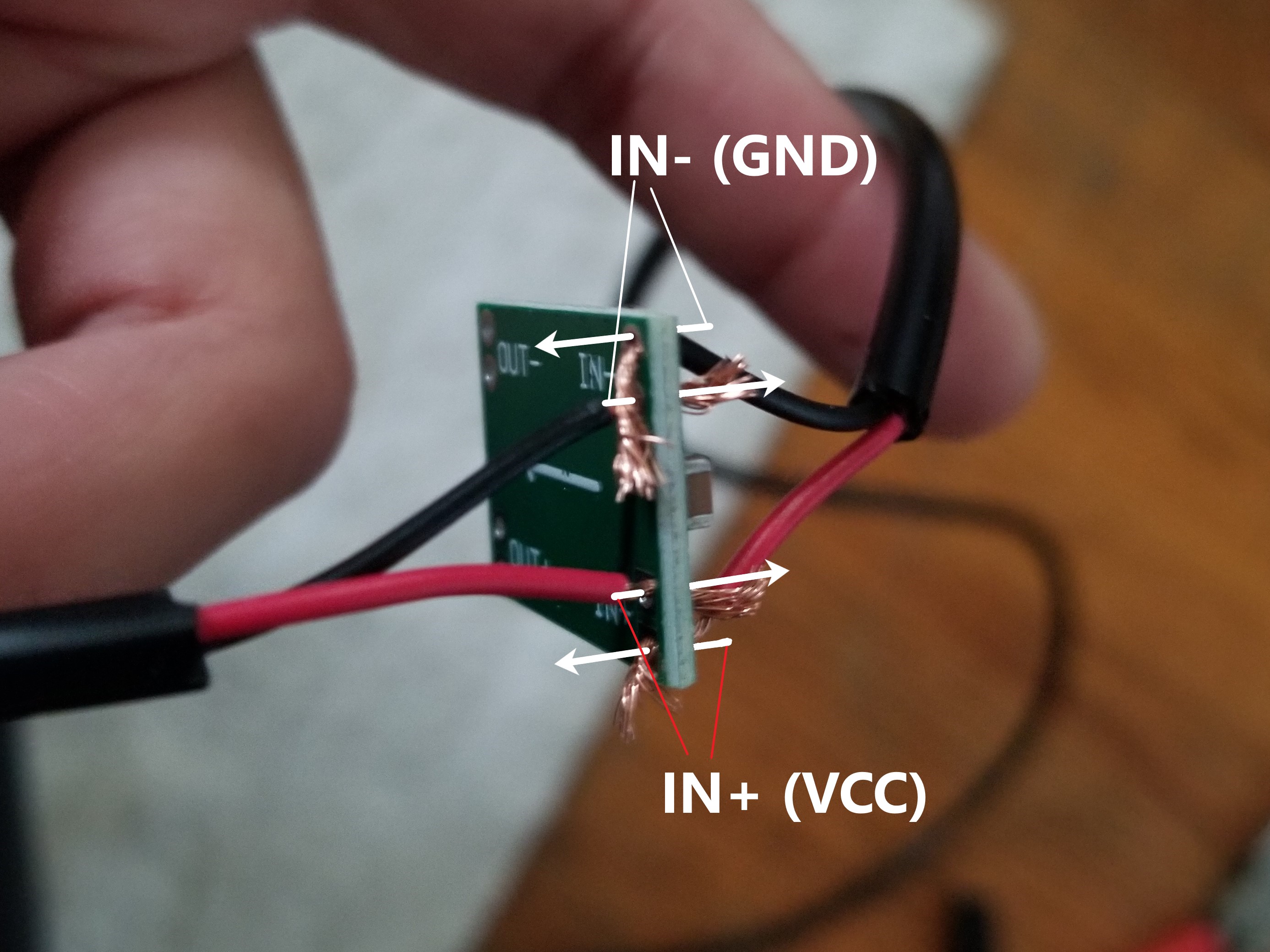
Once the wires were appropriately inserted, I twisted the cut ends together, then soldered both holes together. The twisting-then-soldering ensured a more solid connection.
The (sparse) documentation doesn’t really give any instructions, but I could glean the adjustment procedure from the buyer reviews. You can’t know the output voltage until you supply the input voltage, so I connected the regulator cord to the 24V power supply.
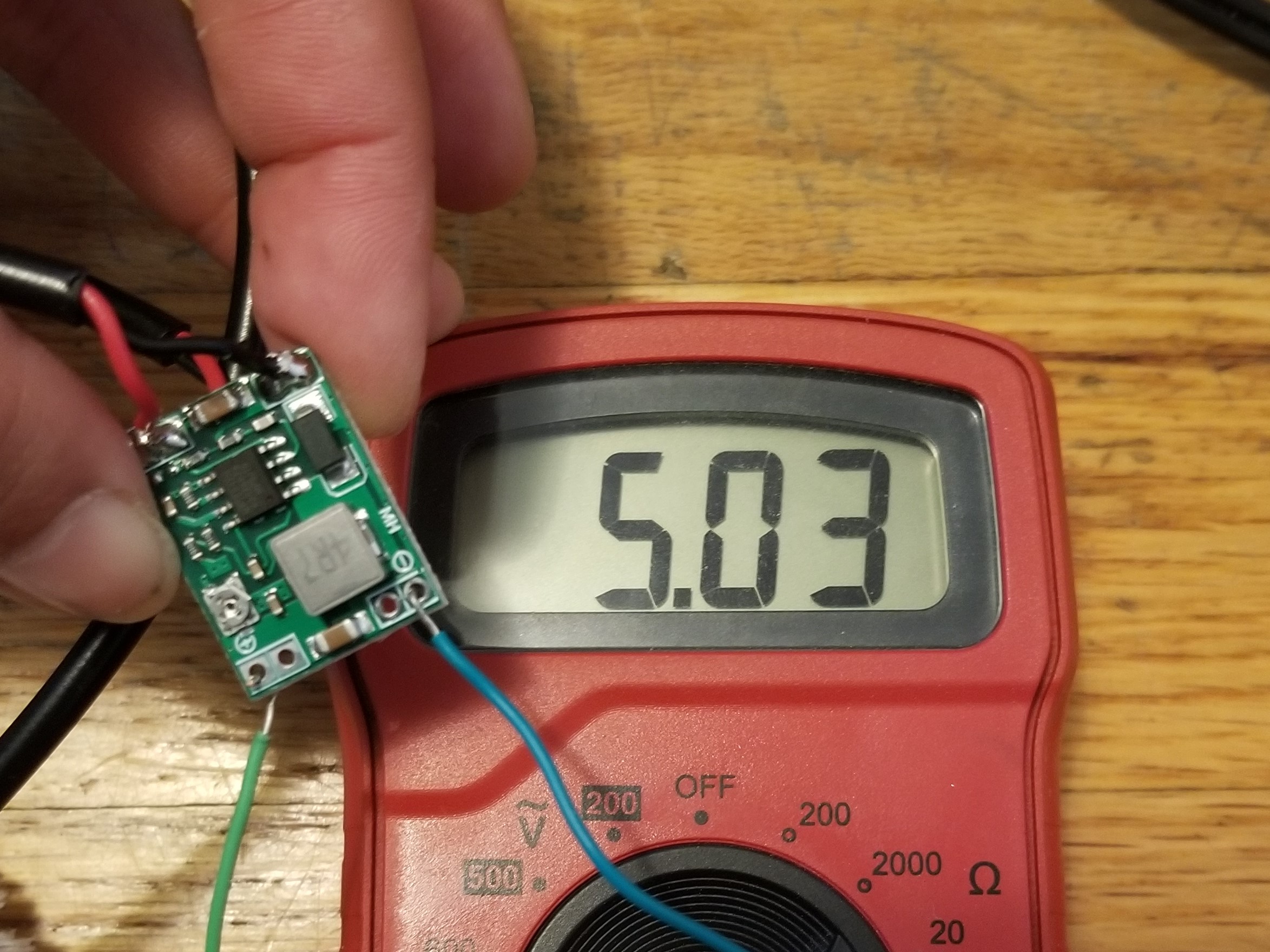
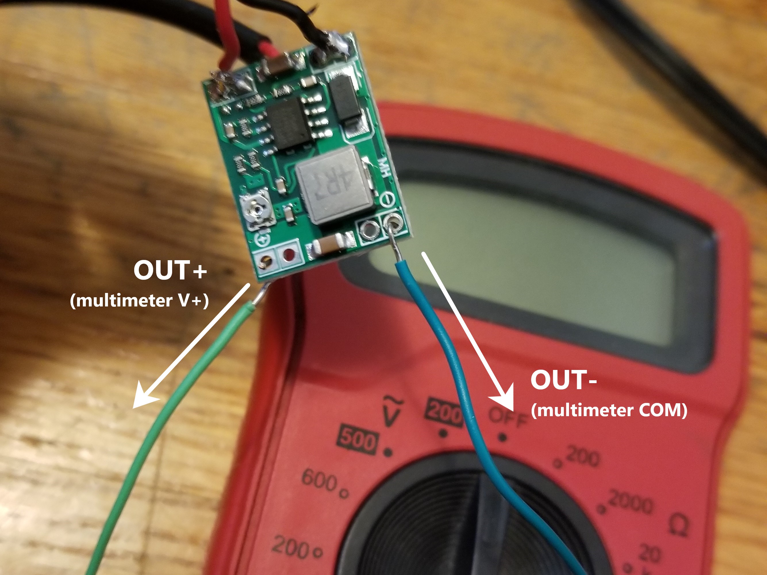
I grabbed my multimeter, put it on DC voltage measurement, and connected the two leads to the regulator’s OUT connections.
[NOTE: one of the reviews warns against adjusting the output voltage this way, on an open circuit without any load. I was fine, but if this is a concern, you can connect a decent-size resistor (3-5kΩ) across OUT along with the multimeter leads.]
The regulators all ship with some random output voltage, since the trim pot on the board is positioned somewhere in the middle of its range.
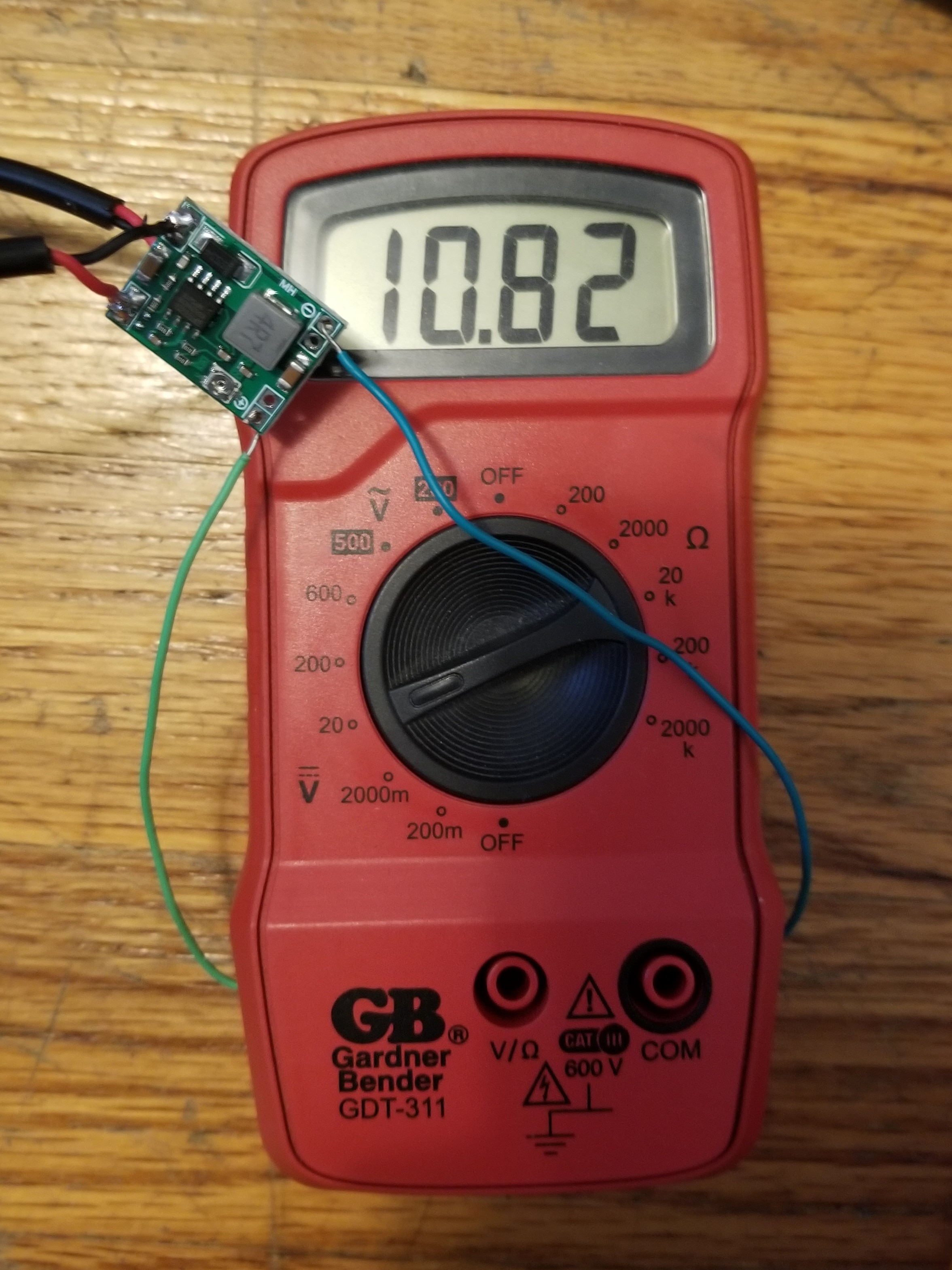
I found a flat-head screwdriver more effective than a Phillips-head for actually turning the trim pot, but your mileage may vary. There aren’t any set divisions on the trim pot to set a particular voltage, so you have to rely on manual dexterity to turn the tiny plate to just the right position. At the same time, watch the reading on the multimeter to see how close you’re getting to the right output voltage.
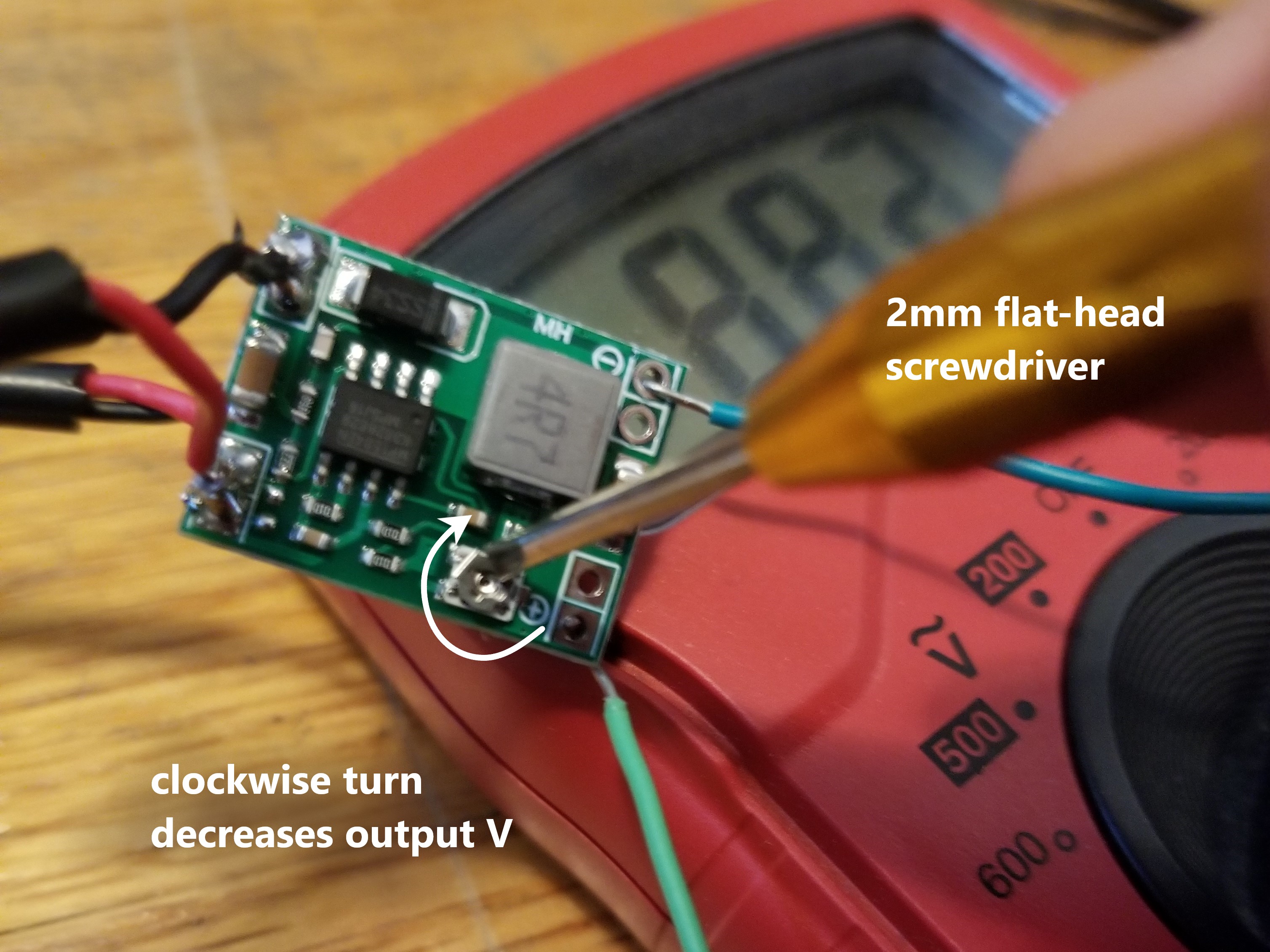
I decided 0.03V away from 5V was close enough.
Once the output voltage was set, I connected a micro-USB cable on the OUT side of the regulator.
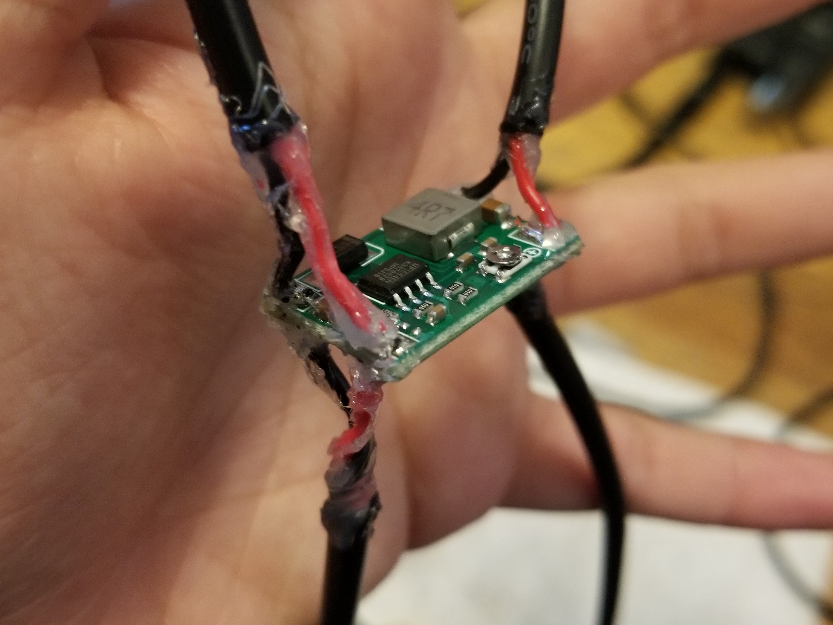
Here, having two holes per connection point came in handy again, as I could solder two micro-USB cables to the OUT connections and thus power two ESP32’s from the same supply.
And hot glue to insulate the whole thing, for maximum jank.
[[electronics]] [[not-research]]