Shanel Wu
They/them. PhD student: smart textiles, weaving, computational craft, hardware hacking.
Serial MP3 player + ESP32 + speakers
by S
Trying out sound-based interactions for a new project (more on the project itself another day, perhaps). Through helping a student with an interactive music/light sculpture a few weeks back, I became aware of several MP3 audio interfaces for Arduinos, and it seemed like a low-cost way (in terms of money and development time) to add sound into my physical computing repertoire.
Components
This project is being developed on a tight turn-around time, so unfortunately, Amazon was my best option for plentiful, cheap components. Parts list:
- ESP32 dev board
- Serial MP3 player
- 32GB SD cards (SDHC)
- Mini speakers
- Jumper wires (most of the boards came with some free jumper wires in the package)
Every resource I reference will be fully listed at the end of this post.
Interfacing ESP32 and MP3 player
As I saw in the Amazon reviews, and later in the Arduino library docs as well, the YX5300 chip that powers the serial MP3 player isn’t very well documented. I suspect the chip is a pretty old design, so any patents/trademarks might have expired or perhaps were always lost to time. Anyway, tangent. The most thorough documentation I’ve found has been put together by people who had also purchased the board, and wanted to put together something more useful than the “official” user manual you get from sellers.
Here’s the link to the page I ended up referring to most, by the author of the YX5300 Arduino library I used: https://majicdesigns.github.io/MD_YX5300/index.html
SD card formatting
Following the documentation, I checked that the SD card was formatted with a FAT32 system before dropping any files in, cleared its memory, then created a folder named 00. The documentation recommended writing all the files to the SD card at once, so I actually also created a 00 folder on my computer’s hard drive where I could set up all of the music files, then copy the contents to the SD card. The YX5300 can play MP3 and WAV files, so some file sources I used:
- Free MP3 for downloading songs in MP3 format
- Freesound.org for downloading free-to-use sound effects and field samples (mostly WAV’s)
Once I had all the files I wanted, I had to rename them each with a 3-digit prefix, which the YX5300 would use to index the files. I’m still figuring out the quirks of the chip’s file handling, because you’ll see the code reference the folder as 1 while I had to name the folder 00. Probably could just script this for the next batch of files.
Minimal Arduino sketch example with full debugging output
The Arduino library is listed as MD_YX5300 in the library manager. Source repo: https://github.com/MajicDesigns/MD_YX5300. The “Simple Player” example code still required an external button component, so I pared it down even more for my “silly simple” set-up.
This code should simply start the MP3 player if everything’s correctly wired up, and will play each file in the folder 00 in order, looping through the folder indefinitely.
/*
 * Modified from MD_YX5300 Simple Player example code.
 * by: Shanel (S) Wu
 *
 * Library dependencies:
 *  - MD_YX5300
 *  - no other dependencies, due to modifications
 *
 * MP3 "player" has the following functions:
 *  - Start/pause track playback with switch (press)
 *  - Run state shown using LED indicator
 *
 * All tracks need to be placed in folder PLAY_FOLDER (defined below)
 * on a micro SD card formatted with FAT32 file system.
 */

#include <MD_YX5300.h>

// Connections for hardware serial interface to the YX5300 module
// use ESP pins 17 and 16 for RX/TX2
//const uint8_t HARDWARE_RX = 16;      // connect to TX of MP3 Player module
//const uint8_t HARDWARE_TX = 17;      // connect to RX of MP3 Player module

#define Console Serial      // aliasing serial communication w/ IDE
#define MP3Stream Serial2   // aliasing serial communication w/ module

// ESP pins config
const uint8_t PIN_LED = LED_BUILTIN;  // LED to show status
const uint8_t PIN_SWITCH = 33;        // play/pause toggle digital pin, active low (PULLUP)

const uint8_t PLAY_FOLDER = 1;        // tracks are all placed in the folder named '00'

// Debug switch for debugging output - set to non-zero to enable
#define DEBUG 1

#ifdef DEBUG
#define PRINT(s,v)    { Console.print(F(s)); Console.print(v); }
#define PRINTX(s,v)   { Console.print(F(s)); Console.print(v, HEX); }
#define PRINTS(s)     { Console.print(F(s)); }
#else
#define PRINT(s,v)
#define PRINTX(s,v)
#define PRINTS(s)
#endif

// global variables
MD_YX5300 mp3(MP3Stream);

// system state
bool playerPause = true;  // true if player is currently paused
uint8_t vol;              // current audio volume

void setup() {
#if DEBUG
  Console.begin(57600);
#endif
  PRINTS("\n[MD_YX5300 Silly Simple Player]\n");

  // set the hardware pins
  pinMode(PIN_LED, OUTPUT);
  pinMode(PIN_SWITCH, INPUT_PULLUP);

  setStatusLED();   // LED should start off, because player starts paused

  // initialize global libraries
  MP3Stream.begin(MD_YX5300::SERIAL_BPS);

  if (!MP3Stream) { // If the object did not initialize, then its configuration is invalid
    PRINTS("Invalid serial pin configuration, check config");
    while (1) { // Don't continue with invalid configuration
      delay (1000);
    }
  } else {
    PRINTS("Serial2 has been set up");
  }

  // send handshake to MP3 player
  PRINTS("\nBeginning MP3 player...");
  mp3.begin();
  PRINT("\nStatus code: ", mp3.getStsCode());

  mp3.setSynchronous(true);

  vol = mp3.volumeMax(); // max seems to be 30, and higher values does not affect it
  PRINT("\nSetting volume to max: ", vol);
  bool b = mp3.volume(vol);
  PRINT(" result ", b);

  mp3.playFolderRepeat(PLAY_FOLDER); // this WILL start playing music
  playerPause = false;
}

void loop() {
  mp3.check();        // run the mp3 receiver
  setStatusLED();     // set the status LED to current status
}

void setStatusLED(void) {
// set the status led - on for running, off for paused
  if (playerPause)
    digitalWrite(PIN_LED, LOW);
  else
    digitalWrite(PIN_LED, HIGH);
}
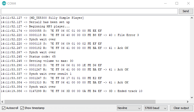
To enable full debugging serial output from the library implementation itself, I had to add the library source files to the Arduino sketch (MD_YX5300.cpp and MD_YX5300.h, this copies them) and change the include statement:
Before: #include <MD_YX5300.h>
After: #include "MD_YX5300.h"
Then, in the .cpp file, I was free to set the LIBDEBUG macro to non-zero to enable verbose output of the hexadecimal values passed between the ESP32 and the MP3 board.
With both debug flags set, the serial output looked like the below screenshot on start-up.
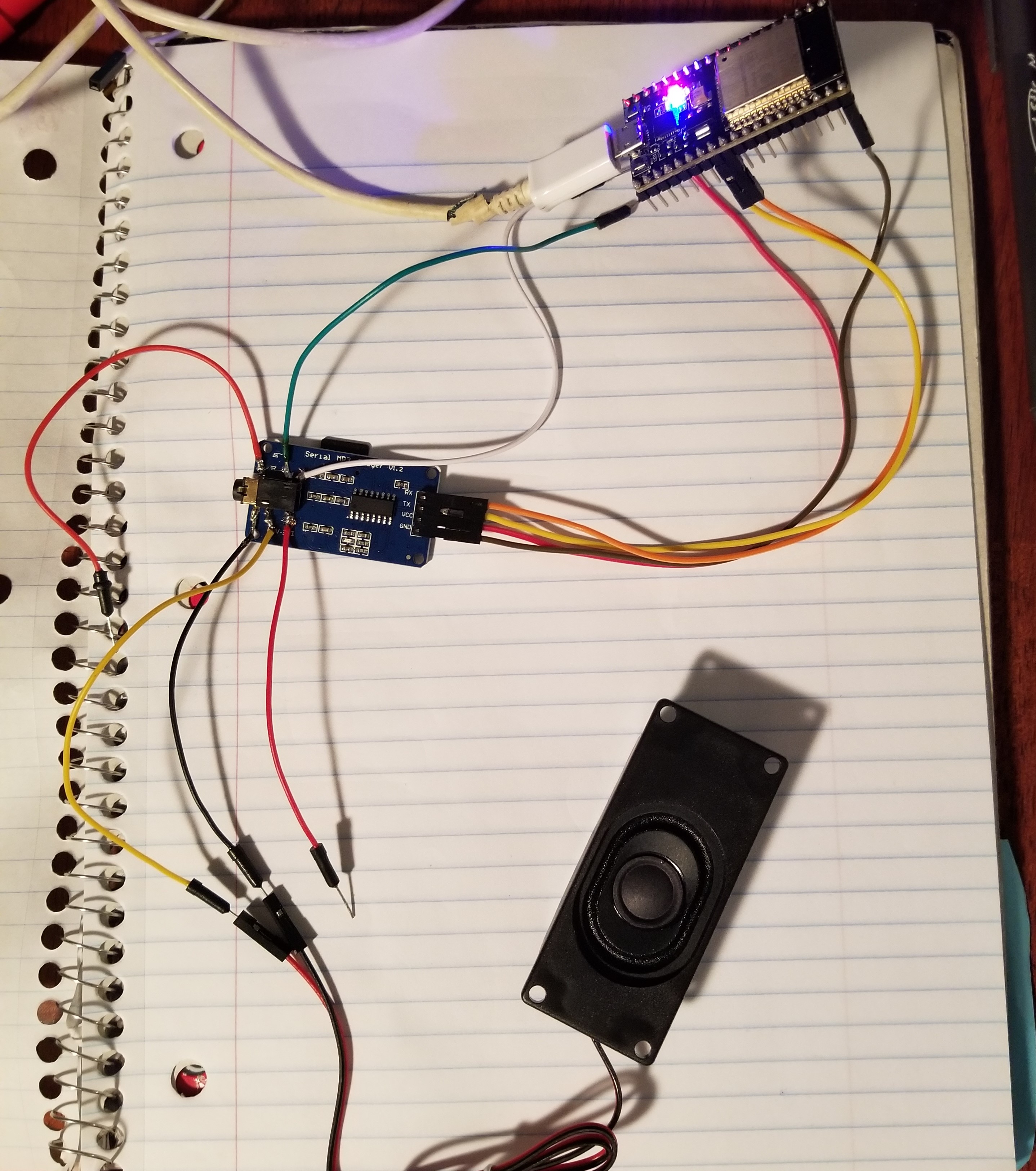
Wiring
The ESP32 pinout I used: [Reddit post]. I connected the RX and TX pins of the MP3 board to pins 17 and 16 of the ESP32, respectively. Pins 16 and 17 are also aliased as RX2 and TX2 of the ESP, a.k.a. the microcontroller’s Serial2 hardware serial interface.
Initially, I had the MP3 board connected to regular GPIO pins on the ESP32 (pins 34 and 35) because the original example code offered software serial as an option. But being a newbie to software serial, I didn’t understand that it was less reliable than hardware serial, and I wasn’t able to get the ESP32 to transmit anything to the YX5300. Oddly enough, I noticed that the ESP32 could RECEIVE data from the YX5300, since it would be able to print the unprompted messages that the chip would send, like when the SD card was removed/replaced.
The board comes with a built-in 3.5mm audio jack that supports stereo outputs, so I was able to borrow a set of wired headphones (what a novelty in these Airpod-dominated times) and verify that music was playing.
Wiring speakers without an audio jack
The speakers I had purchased as cheap testers came with two wires that could connect to header pins, not a 3.5mm plug. I had to do a surprising amount of digging to figure out the pinout of the built-in audio jack. Ultimately, I found a very similar component on AliExpress which had a detailed schematic.
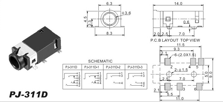
I had no idea what was going on with the electrical diagram, but this page from a component manufacturer was super helpful: Understand Audio Jack Switches and Schematics. In the end, the most useful approach was to just solder jumper wires to each of the 6 pads and try connecting them to the speaker.
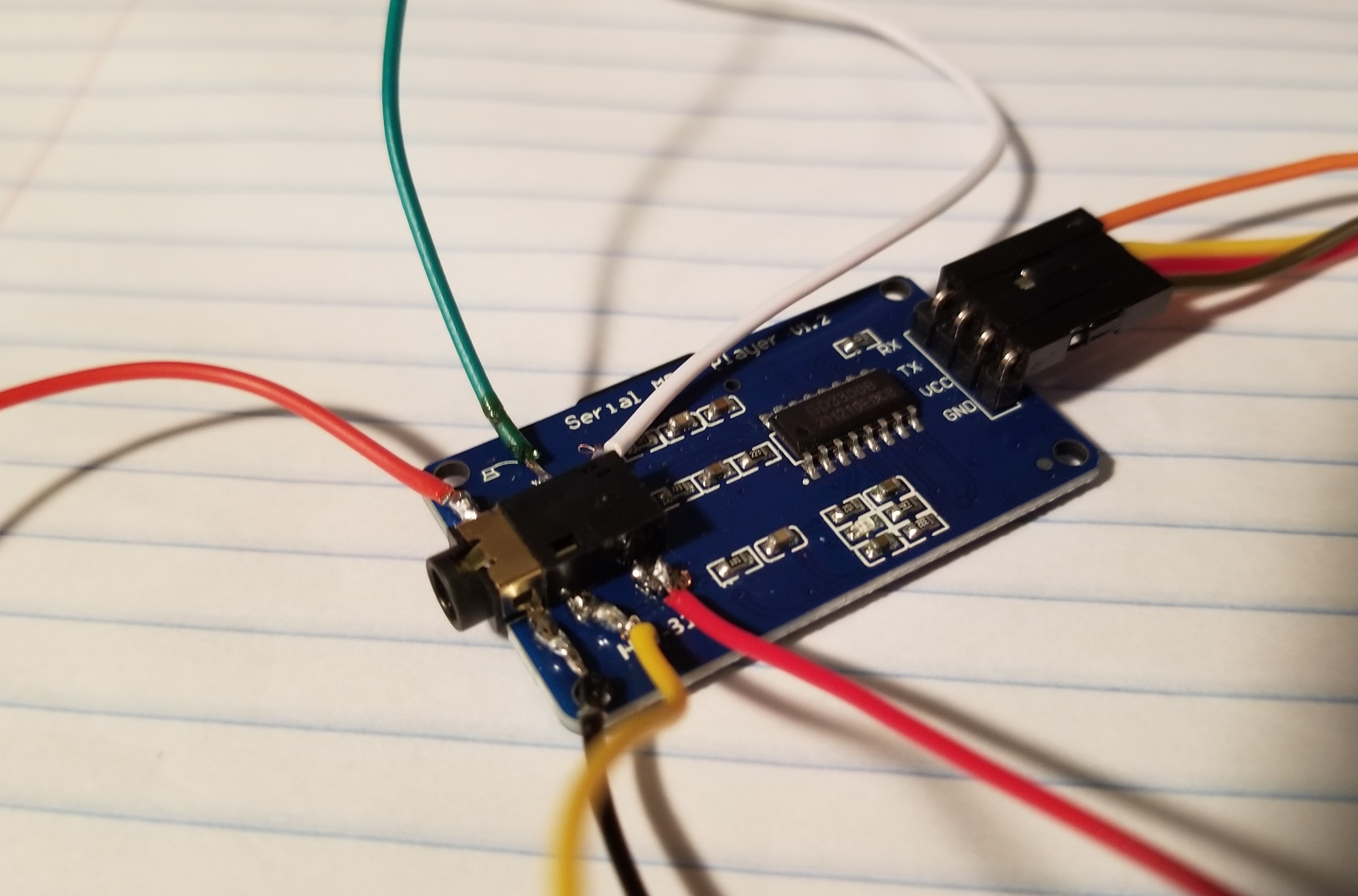
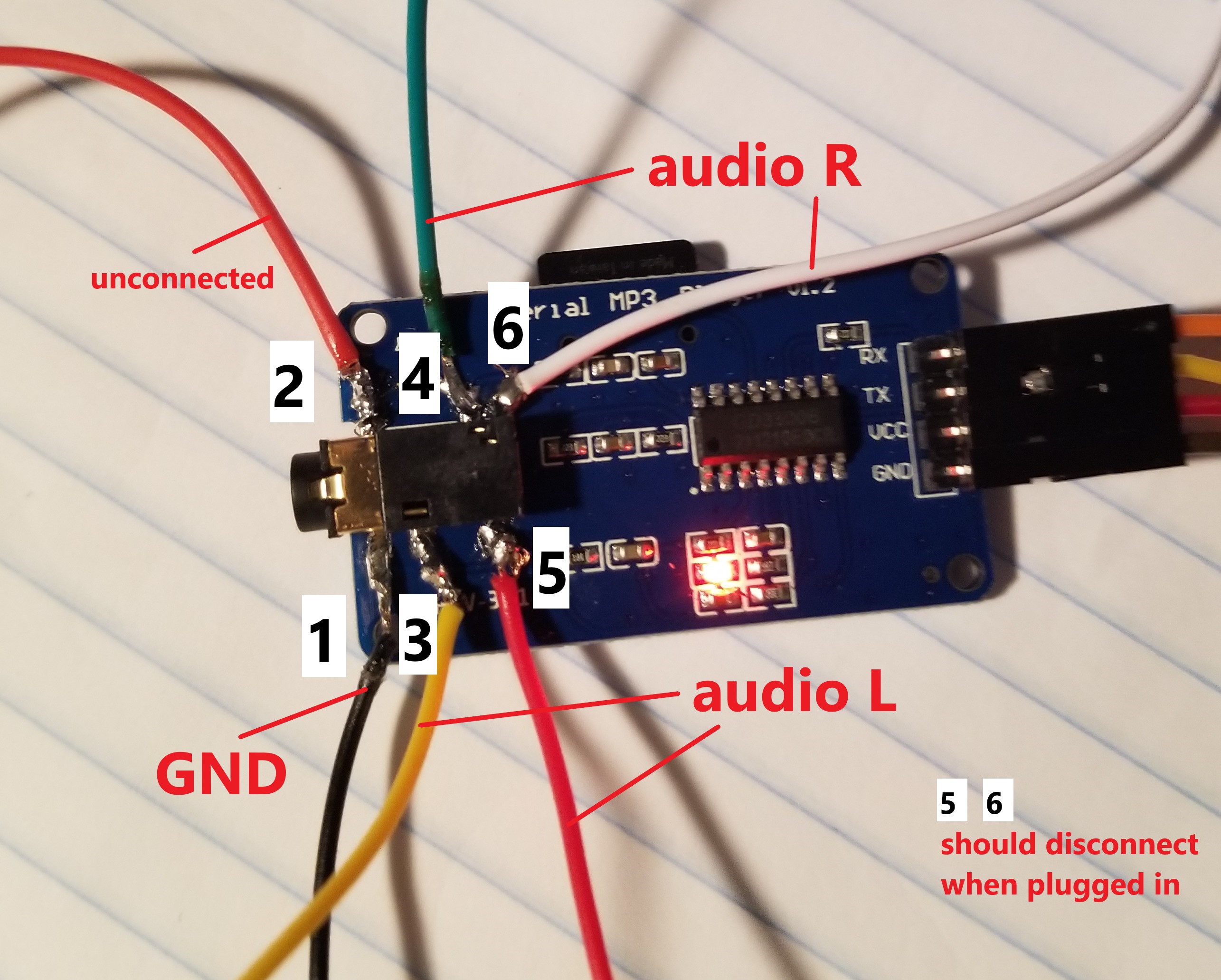
Prior to soldering, I did find which wire was ground, which is why I knew to solder a black wire to the lower left pad for easier identification. At this point, my next step was to whip up a crappy audio amplifier circuit so that the speakers would be loud enough to hear without strapping them to my ears. But that’ll be next post.
References
- YX5300/serial MP3 player user manual from seller - https://m.media-amazon.com/images/I/81xDdQx7soL.pdf
- Community-contributed documentation for Arduino library and YX5300 chip - https://majicdesigns.github.io/MD_YX5300/index.html
- ESP32 pinout - https://www.reddit.com/r/esp32/comments/b5mkag/a_better_pinout_diagram_for_esp32_devkit/
- Community-contributed Arduino library source - https://github.com/MajicDesigns/MD_YX5300
- Sites for downloading free sound files:
- MP3 songs - https://vww.freemp3cloud.com/
- Sound effects, samples, etc. (mostly WAV) - https://freesound.org/
- Explainer page on audio jack pinouts and schematics - https://www.cuidevices.com/blog/understanding-audio-jack-switches-and-schematics